Carbon Capture - description
Process model description
The purpose of the carbon capture LIBPF® process model is to evaluate different carbon capture technologies applicable to conventional fossil-fuelled power plants to reduce the carbon dioxide emissions associated with the production of electric energy.
The models represent the production of electrical energy from three different fossil fuels as feedstock (natural gas, gasoil and coal) with four different carbon capture systems. The four power plant carbon capture configurations (based on process schemes and basic data from: H Yang, Z Xu, M Fan, R Gupta, R B Slimane, A E Bland, I Wright, Progress in carbon dioxide separation and capture: A review, Journal of Environmental Sciences 20(2008)) are:
- Post-combustion;
- Gasification;
- Oxy-combustion;
- Chemical-looping combustion.
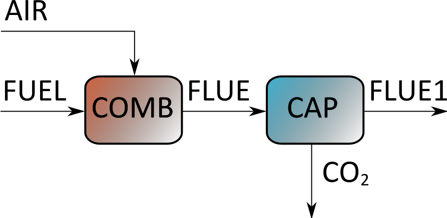
Post-combustion
In this scheme the air and the fuel are reacted in the COMB (energy conversion) section; the flue gas from this section proceeds to the CAP (carbon capture) section where a concentrated CO2 stream is separated from the low-CO2 flumes to stack (FLUE1).
Gasification
In this scheme fuels are first converted into a mixture of CO2 and H2 (SYNGAS) through a reforming or gasification process. A CAP (carbon capture) section extracts a concentrated CO2 stream from the SYNGAS whereas H2 goes to the COMB (energy conversion) section.
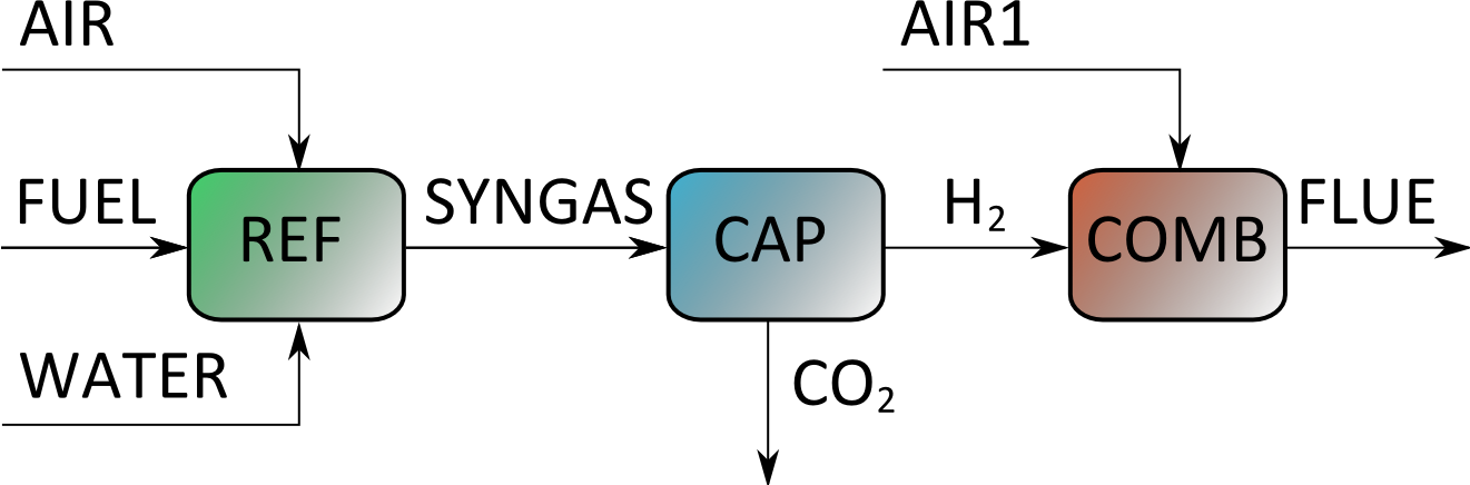
In this scheme the fuel, the water and the optional air are converted in the REF (reformer) unit, then resulting SYNGAS proceeds to the CAP (carbon capture) section where a concentrated CO2 stream is separated from the hydrogen-rich stream that is reacted with air in the COMB (energy conversion) section to yield a carbon-free flue gas to stack (FLUE).
Oxy-combustion
In the oxyfuel combustion (or oxy-firing) scheme N2 (nitrogen) is separated from the AIR steam in an air separation plant AIRSEP, while the technical O2 (oxygen) is sent to the energy conversion section together with the FUEL.

The resulting FLUE stream is high-purity CO2.
Chemical-looping combustion
In the chemical-looping combustion (CLC) or unmixed combustion scheme the transfer of oxygen between air and fuel is performed indirectly by an oxygen carrier such as metal powders: iron, nickel, copper, manganese (in this example iron has been chosen as oxygen carrier). The oxygen carrier moves in the oxidized state (MO) from the oxidation chamber (OXY) to the energy conversion section (COMB) where it is reduced and back to the oxidation chamber in the reduced state (M).
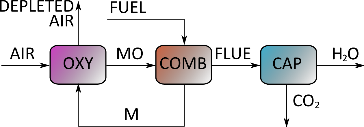
The exhaust gas stream from air reactor (DEPLETED AIR) is harmless, consisting mainly of nitrogen. The exhaust gas (FLUE) from the energy conversion consists of CO2 and H2O, so that the carbon capture system (CAP) is just a condenser. Note: this simplified block diagram does not show the following features, included in the process model: the heat recovery between the cold inlet air stream (AIR) and the hot exhaust gas stream from the oxidation chamber (DEPLETED AIR), set to bring the latter temperature down to 200 °C; the metal makeup and purge required in the real world to control the maximum temperature in the system, avoid accumulation of solid impurities and to avoid numerical singularity - this recycle stream is set to obtain a temperature in the oxidation chamber of 1500°C.
Feedstock
Three different fossil fuels have been considered as feedstock: natural gas, gasoil and coal.
The assumed fuel compositions are:
- Natural gas, on molar basis: CH4 95%, CO2 3%, N2 2%
- Gasoil (using pure n-Hexadecane with a boiling point of 287 °C as representative of the boiling range of gasoils: 270 ÷ 300°C): C16H34 100%
- Coal, on mass basis: C 95%, H 1%, ASH 4%
- Ambient air, on molar basis: N2 79%, O2 20%, H2O 1%
Sub-section modelling
To maximize re-use, the process models are assembled using standard sub-units: reformer, conversion, separation. These are based on very simple process models for the sections, without specifying the scale or which technology is actually used.
** Reformer **
The reformer submodel has three inlets: fuel, an optional air stream and water. The gasoil and coal fuels are first converted using the following fictitious reactions to lighter, gas phase components, with unit conversion: C16H34 + 8·H2O → 8·CH4 + 8·CO + 9·H2 C + H2O → CO + H2
Next the reforming and gas-shift reactions are simultaneously computed at their thermodynamic equilibrium at 600 °C: CH4 + H2O → CO + 3·H2 CO + H2O → CO2 + H2 There is just one outlet, the syngas, released at 600° C.
** Conversion **
The conversion submodel has two inlets: fuel and an oxidant stream. The energy conversion unit could equally well represent gas turbines, internal combustion engines, combined cycles or fuel cells. What is assumed is a user-supplied thermal-to-electrical energy yield η (eta = 50% by default), and complete oxidation of the fuel(s) to water and carbon dioxide: CH4 + 2·O2 → CO2 + 2·H2O H2 + ½·O2 → H2O CO + ½·O2 → CO2 C16H34 + 24½·O2 → 16·CO2 + 17·H2O C + O2 → CO2 EGR (exhaust gas recirculation) is not considered. At the exit of the oxidation reactor the reaction products at 200 °C are isothermally split, routing all metal and metal oxide to an optional “metal” outlet stream, whereas the remaining materials proceed to the “fluegas” outlet.
** Separation **
The general-purpose separation section takes a single inlet air, syngas or fluegas and splits it in two outlets: a depleted stream and an enriched stream, both at 200°C. The unit is generic in the sense that the user specifies the index of the component that is to be separated, and the fineness of separation for this component based on recovery and molar purity. The unit is also generic in the sense that it could equally well represent a membrane, chemical absorption or solid adsorption separation. The energy cost of the separation in fact is empirically correlated to:
- the change in gas temperature to bring the inlet stream to the outlet temperature of 200°C
- the change in entropy of mixing associated with the separation:
%DELTA S = {left lbrace dot n cdot R cdot %SIGMA x_i * log(x_i) right rbrace}{outlets} - {left lbrace dot n cdot R cdot %SIGMA x_i * log(x_i) right rbrace}{inlet}
The resulting expression:
power = T cdot %DELTA S cdot %alpha - duty / %beta
is parametrized by the two empirical coefficients %alpha (default value 2) and %beta (default value 5) which can be tuned to represent any separation.
Results and conclusion
The results for the KPI (key performance parameters) are:
| Configuration | Fuel | η (efficiency) | specific CO2 emission, g/kWh |
| pre | coal | 40.5% | 328 |
| natural gas | 44.7% | 233 | |
| gasoil | 44.5% | 557 | |
| post | coal | 40.1% | 48 |
| natural gas | 41.2% | 25 | |
| gasoil | 41.0% | 31 | |
| oxy | coal | 48.2% | 40 |
| natural gas | 48.2% | 21 | |
| gasoil | 48.2% | 26 | |
| clc | coal | 45.0% | 43 |
| natural gas | 43.5% | 23 | |
| gasoil | 43.9% | 29 |
where η is the overall electrical efficiency and CO2 is the carbon dioxide emission in g per unit electrical energy produced. The results are of a qualitative nature because some tuning would be required to have each subunit represent accurately the actual conversion or separation processes that con be realized.