Detailed process model description for electrolysis demo
Model specification
Introduction
Intended audience
The present document is oriented to:
-
Model developers
-
Model users
-
System Integrators.
Scope
The scope of the present document is to describe the capabilities of the Electrolysis demo, for the process modeling of continuous alkaline electrolysis systems for hydrogen production.
Prerequisites
-
basic knowledge of process engineering and / or of chemical reactions processing.
-
know about the different roles involved with the lifecycle of solutions developed using the LIBPF® enabling technology, see LIBPF® Technology Introduction
Electrolysis kernel
In LIBPF® one kernel can support many process models, each as a different flowsheet type.
All the process models supported by a kernel share the same list of components and can use all LIBPF® embedded types plus the custom types registered by the kernel itself.
Type list
The Electrolysis kernel registers the following process models, based on the built-in LIBPF® FlowSheet type:
| Type | Name | Description | options | Note |
|---|---|---|---|---|
| Elysim | Elysim | Alkaline electrolysis system for hydrogen production | STACK:multiReactions[0].H: Stack cell length |
default model type |
STACK:multiReactions[0].W: Stack cell width |
||||
STACK:multiReactions[0].nCells: Number of cells in the stack |
||||
S05:Tphase.mdot: Estimate for H2 side electrolyte recycle |
||||
S06:Tphase.mdot: Estimate for O2 side electrolyte recycle |
Component list
The fluids to be processed are broken down in their constituents and represented as a mixture of basic components.
The components are defined using built-in LIBPF® basic types if possible, or with custom components.
More precisely the Electrolysis kernel defines the following component list (click on the component type to jump to the reference documentation for the component):
| Type | Name | Description |
|---|---|---|
| purecomps::H2O | water | standard model for water |
| purecomps::H2 | molecular hydrogen | electrolysis product |
| purecomps::O2 | molecular oxygen | electrolysis product |
| KOH | potassium hydroxide | catalyst |
Process description and scheme
The underlying process model is based on the publication: Mónica Sánchez, Ernesto Amores, David Abad, Lourdes Rodríguez, Carmen Clemente-Jul, “Aspen Plus model of an alkaline electrolysis system for hydrogen production”, International Journal of Hydrogen Energy, Volume 45, Issue 7, 2020, Pages 3916-3929 (doi: 10.1016/j.ijhydene.2019.12.027).
PFD
The following Process Flow Diagram should clarify the process.
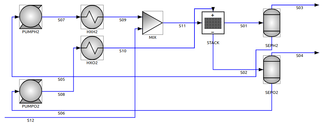
The cell stack (STACK) is the heart of the system. Electricity is supplied to the cell stack to decompose water into hydrogen and oxygen: hydrogen is released at the cathode (S01) and oxygen is released at the anode (S02). Also certain side-reactions take place, the most important being the cross-flow of hydrogen to the anode.
Only about two thirds of the supplied electric power is electrochemically converted, the rest is released as heat in the cell stack, which has to be cooled to keep it at the correct operating temperature. The cooling of the cell stack is effected by circulating a large excess of electrolyte solution, separately at the two electrodes (S10 and S11), so that the water conversion per pass is effectively very low (in the range of 0.5%).
Due to the low water conversion per pass though the stack, the cathode and anode outlets (S01 and S02) do not contain only the produced gases, but also the excess circulating electrolyte. To recover the hydrogen (S03) and vent the oxygen (S04) so that the system pressure is kept low, the cathode and anode outlets are sent to two separate liquid-gas separation vessels (SEPH2 and SEPO2).
The degassed electrolyte is returned back to the stack by separate recirculation pumps (PUMPH2 and PUMPO2) and cooled in separate heat exchangers HXH2 and HXO2.
The water consumption due to the electrochemical reaction is compensated with a deionized water make-up (S12), so that the water hold-up in the circuit is constant.
Stream list
The streams are defined using built-in LIBPF® basic types.
Click on the type to jump to the reference documentation for the stream.
| Type | Name | Description | From | To |
|---|---|---|---|---|
| StreamIdealLiquidVapor | S01 | H2 cathode outlet | STACK catout | SEPH2 in |
| StreamIdealLiquidVapor | S02 | O2 anode outlet | STACK anout | SEPO2 in |
| StreamVapor | S03 | H2 production | SEPH2 vapor | sink in |
| StreamVapor | S04 | O2 production | SEPO2 vapor | sink in |
| StreamLiquid | S05 | H2 side cathode electrolyte | SEPH2 condensate | PUMPH2 in |
| StreamLiquid | S06 | O2 side anode electrolyte | SEPO2 condensate | PUMPO2 in |
| StreamLiquid | S07 | Pumped H2 side cathode electrolyte | PUMPH2 out | HXH2 in |
| StreamLiquid | S08 | Pumped O2 side anode electrolyte | PUMPO2 out | HXO2 in |
| StreamLiquid | S09 | Cooled H2 side cathode electrolyte | HXH2 out | MIX in |
| StreamIdealLiquidVapor | S10 | Cooled O2 side anode electrolyte and anode inlet | HXO2 out | STACK anin |
| StreamLiquid | S12 | Water make-up | source out | MIX in |
| StreamIdealLiquidVapor | S11 | Cathode H2 inlet | MIX out | STACK catin |
Unit list
The unit operations are defined using built-in LIBPF® basic types if possible, or with custom unit models.
Click on the type to jump to the reference documentation for the unit operation.
| Type | Name | Description |
|---|---|---|
| Electrolyzer | STACK | Electrolysis stack |
| FlashDegasser<StreamIdealLiquidVapor> | SEPH2 | Hydrogen separator |
| FlashDegasser<StreamIdealLiquidVapor> | SEPO2 | Oxygen separator |
| Pump | PUMPH2 | Electrolyte circulation pump cathode side |
| Pump | PUMPO2 | Electrolyte circulation pump anode side |
| AirCooler | HXH2 | Electrolyte cooling cathode side |
| AirCooler | HXO2 | Electrolyte cooling anode side |
| Mixer | MIX | Electrolyte mixer |
The Electrolyzer model is defined as a superclass of the built-in MultiExchanger model (a rating, optionally reactive multi-Stream heat exchanger), customized with three reactions:
-
MultiReactionH2O: Electrochemical reaction for water electrolysis2*H2O = H2 + 0.5 O2 + H2O (c) (c) (a) (a) -
MultiReactionHTO: Crossover of hydrogen to the oxygen sideH2 = H2 (c) (a) -
MultiReactionCrossFlow: Crossover of water from cathode to anode sideH2O = H2O (c) (a)
The Aircooler model is defined as a superclass of the built-ins:
-
FlashDrum model (a Flash drum with many inlets and one outlet that can be used as a simple heat exchanger model)
-
and the ElectricalConsumption mixin which converts power to current / voltage.
that allows to specify a COP (coefficient of performance) to have it compute the electrical consumption.
Model limitations
At this time the process model has a number of limitations:
-
It only qualitatively reproduces the results of the base case of Sánchez et al.
-
Rather than implementing the full polarization curve, an empirically fit value for the areic resistance is employed
-
The potassium hydroxide properties mimics those of sodium hydroxide.
-
The water traps are not represented.
-
The following variables are fixed:
-
conversion of the electrochemical and cross-flow reactions
-
stack solid temperature
-
“potassium hydroxide” concentration in the electrolyte
-
In a subsequent version these limitations will be lifted.