Detailed process model description for cogeneration plants
Model specification
Introduction
Intended audience
The present document is oriented to:
-
Model developers
-
Model users
-
System Integrators.
Scope
The scope of the present document is to describe the capabilities of the Cogeneration demo, for the process modeling of stationary energy cogeneration power plants (Combined Heat and Power plants, CHP).
Cogeneration plants, or Combined Heat and Power plants (CHP) simultaneously produce electric energy and low-temperature thermal energy.
From Wikipedia: “Cogeneration is a more efficient use of fuel or heat, because otherwise-wasted heat from electricity generation is put to some productive use. Combined heat and power (CHP) plants recover otherwise wasted thermal energy for heating … Small CHP plants are an example of decentralized energy … Gas turbine CHP plants using the waste heat in the flue gas of gas turbines. The fuel used is typically natural gas.”
Prerequisites
-
basic knowledge of process engineering and / or of thermoelectric energy generation processes.
-
know about the different roles involved with the lifecycle of solutions developed using the LIBPF® enabling technology, see LIBPF® Technology Introduction
Cogeneration kernel
In LIBPF® one kernel can support many process models, each as a different flowsheet type.
All the process models supported by a kernel share the same list of components and can use all LIBPF® embedded types plus the custom types registered by the kernel itself.
Type list
The Cogeneration kernel registers the following models, based on the built-in LIBPF® FlowSheet type:
| Type | Description | options |
|---|---|---|
MicroTurbineC30 |
30 kW micro-turbine power generation unit matching C30 | |
MicroTurbineOpen |
as MicroTurbineC30 but with hot air inlet and compressed air outlet |
|
MicroTurbine |
parametrized micro-turbine power generation unit | turbine model = C30 (default), C65, C200, C1000 |
Cogeneration |
Cogeneration with configurable micro-turbine | turbine model = C30 (default), C65, C200, C1000 |
CogenerationICE |
Cogeneration with Internal Combustion Engine | |
Burner |
Complete combustion of hydrocarbons, hydrogen and carbon monoxide | |
DeltaT |
Compute the adiabatic combustion temperature of a fuel | |
DeltaH |
Compute the lower heat of combustion of a fuel |
Component list
The fluids to be processed are broken down in their constituents and represented as a mixture of basic components.
The components are defined using built-in LIBPF® basic types.
More precisely the Cogeneration kernel defines the following component list (click on the component type to jump to the reference documentation for the component):
| Type | Name | Description |
|---|---|---|
| purecomps::water | water | standard model for water |
| purecomps::N2 | N2 | standard model for nitrogen |
| purecomps::O2 | O2 | standard model for oxygen |
| purecomps::methane | CH4 | standard model for methane |
| purecomps::CO | CO | standard model for carbon monoxide |
| purecomps::CO2 | CO2 | standard model for carbon dioxide |
| purecomps::H2 | H2 | standard model for hydrogen |
Fuel streams are by default a mixture of methane (98% b.v.) and nitrogen but their composition can be changed to any mixture of methane, carbon monoxide, hydrogen and nitrogen, to cover a wide range of lean fuels, syngas and biogas.
Process descriptions and schemes
Microturbine
The microturbine models represent stationary, single-shaft gas turbines operated according to a recuperated Brayon cycle, with different electric power outputs: 30 kW, 65 kW, 200 kW and 1000 kW (obtained assembling four 250 kW units in parallel).
The model quantitatively reproduces the nominal performance and part-load behavior of a commercial unit available from a leading vendor (Capstone Turbine Corporation, “Technical Reference - Capstone Model C30 Performance” 410004 Rev. D, April 2006).
Stream list
The streams are defined using built-in LIBPF® basic types.
Click on the type to jump to the reference documentation for the stream.
| Type | Name | Description | From | To | options |
|---|---|---|---|---|---|
| StreamVapor | S01 | Air feed | source out | C in | |
| StreamVapor | S02 | Fuel feed | source out | RX in | |
| StreamVapor | S03 | Turbine Inlet | RX out | T in | |
| StreamVapor | S04 | Turbine Outlet | T out | HX | hotin |
| StreamVapor | S05 | Compressed Air and HX cold inlet | C out | HX | coldin |
| StreamVapor | S06 | HX cold outlet and RX burner inlet | HX | coldout | RX in |
| StreamVapor | S07 | Recuperator exhaust | HX | hotout | sink in |
Unit list
The unit operations are defined using built-in LIBPF® basic types and the Burner type provided by the kernel.
Click on the type to jump to the reference documentation for the unit operation.
| Type | Name | Description | options |
|---|---|---|---|
| Compressor | T | Turbine | |
| Compressor | C | Compressor | |
| Burner | RX | Burner | |
| Exchanger | HX | Turbine recuperator |
The system is fed with:
-
Ambient air (S01) at ISO conditions: 15 °C, 60% relative humidity (1 % v/v water content) and 101325 Pa (standard sea level pressure)
-
High Pressure Natural Gas (S02): 99% CH4, 1% N2.
All streams are gas-phase.
PFD
The following Process Flow Diagram should clarify the process.
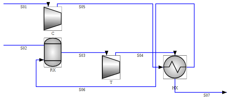
The ambient air (S01) is fed to the compressor unit C, the compressed air (S05) proceeds to the cold side of the recuperator (HX) where it is preheated (S06), then proceeds to the the burner (RX) where the fuel (S02) is added and burned completely (CO, H2 and CH4 total combustion to H2O and CO2).
The hot, pressurized gases (S03) from the burner are fed to the turbine expander (T). The turbine exhaust (S04) proceeds to the hot side of the recuperator (HX) before leaving the system.
Operating conditions
The operating conditions at the nominal point are:
-
air in 38.802009 kmol/h
-
methane in 0.5226831 kmol/h
-
max P = 4 bar
-
discharge pressure 1.01325 bar
-
burner deltaP = 100.0 mbar
-
HX.deltaPhot = HX.deltaPcold = 50 hPa
-
C.ηM = 99% (mechanical efficiency)
-
C.ηE = 100% (electrical efficiency)
-
T.ηM = 99% (mechanical efficiency)
-
T.ηE = 100% (electrical efficiency)
The matching of the model to the vendor-provided nominal key performance parameters:
-
exhaust temperature 275 °C
-
Turbine Inlet Temperature (TIT) 1144 K
-
net electrical efficiency 26 %
are performed by:
-
Matching vendor claimed exhaust temperature by tuning the HX.UA;
-
Matching vendor claimed TIT by tuning the T.θ;
-
Matching vendor claimed net efficiency by tuning the C.θ (this is performed manually).
The result of the matching is:
-
HX.UA = 1428.7 W/K
-
T.θ = 71.9% (thermodynamic isentropic efficiency)
-
C.θ = 85% (thermodynamic isentropic efficiency).
Variable load modeling
For accurate pressure driven modeling at part-load, the relationship between the rotation frequency, pressure and flow should be included, based on the characteristic curves of the turbine and compressor.
This model implements some simple relationships based on adimensional or reduced quantities from A. Capetti, Motori termici , UTET, 1964, I ed. to qualitatively represent the behavior, based on the following assumptions:
-
geometries do not change and load control is achieved by changing the frequency;
-
the operating point of the compressor should be kept clear of the stonewall and surge limits, and move along an optimal curve
-
the corrected mass flows are linear functions of the frequency of both the compressor and the turbine;
-
the turbine will operate at stonewall (incipient choked flow), so that the mass flow does not depend on the pressure ratio;
-
the TIT is constant;
-
the thermodynamic (isentropic) efficiency of the compressor will not change significantly, whereas the thermodynamic efficiency of the turbine varies as a certain function of the reduced frequency
The fresh-air flow is adjusted to keep the actual compressor corrected mass flow equal to the should-be value, and the fuel is adjusted to keep the TIT.
Results
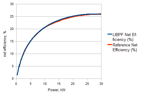
The part-load behavior can be calculated by acting on the compressor set pressure from the nominal value of 4 bar down to 1.65 bar (corresponding to an electrical power of 2 kW). The predicted net efficiency compares well to the vendor data:
The predicted exhaust temperature on the other hand deviates from the vendor data:
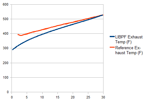
indicating that the assumption that the TIT is kept constant by the control system may not apply.
The model user can also freely change the inlet conditions, the fuel composition (fuels containing CO and H2 can be handled), the unit pressure drops and reaction conversions in the burner.
Model options
This model has no options.
Cogeneration
The Cogeneration flowsheet represents a Combined Heat and Power plant (CHP) whose power generation unit is a micro-turbine.
The waste heat in the turbine flue gas is used as the low-temperature thermal energy source.
The Cogeneration flowsheet can be configured to simulate different micro-turbine models, each with a different electric power output: 30 kW, 65 kW, 200 kW and 1000 kW (the latter obtained assembling five 200 kW units in parallel).
Stream list
The streams are defined using built-in LIBPF® basic types.
Click on the type to jump to the reference documentation for the stream.
| Type | Name | Description | From | To | options |
|---|---|---|---|---|---|
| StreamVapor | S02 | Fuel | source out | Microturbine fuel | |
| StreamVapor | S03 | Hot gases | Microturbine exhaust | Cogenerator in | |
| StreamVapor | S04 | Fumes | Cogenerator out | sink in |
Unit list
The unit operations are defined using built-in LIBPF® basic types and the Microturbine type defined by the kernel.
Click on the type to jump to the reference documentation for the unit operation.
| Type | Name | Description | options |
|---|---|---|---|
| MicroTurbine | Microturbine | Microturbine unit | |
| FlashDrum | Cogenerator | Cogeneration heat exchanger |
PFD
The following Process Flow Diagram should clarify the process:
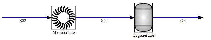
The fuel (S02) is fed to the micro-turbine(s); the thermal energy from the turbine flue gas (S03) is recovered in the Cogeneration heat exchanger; the cogenerator fumes (S04) are then discharged to the atmosphere.
Model options
This model has no options.
CogenerationICE model
The CogenerationICE flowsheet represents a Combined Heat and Power plant (CHP) whose power generation unit is an Internal Combustion Engine.
The waste heat in the engine flue gas is used as the low-temperature thermal energy source.